Intro
We are using the CrossWorks IDE with bundled GCC compiler on my work as company’s standard embedded systems project tool. Nobody had noticed any issues with it until we were working on a project with “slightly higher” demands on waking up time from the sleep mode.

System I mentioned was a STM32L4 (ARM Cortex-M4 core) based solution with the piezo switch as one of the wakeup sources. The button is attached to one of the sensor lines and triggers interrupts when a user presses it. Necessity of speeding up wake up time come due to several reasons:
- our piezo switch asserts MCU’s sensor line only for 100-200 ms when a user presses it in a effortles way without a goal to squeeze it out. If a mechanical button was used, we would not even notice any issues with our app. All mech buttons I have worked with assert a line for more than 500 ms
- piezo button circuit did not include any debounce protection (the reason is not so important now). Due to that there were some spurious wakeups that have to be caught by the app
How we found that issue and overcome it with simple changes in CrossWorks’ CRT (C Runtime) implementation of the standard library I will describe below.
That may be especially interesting for ones who uses the following products:
- CrossWorks for ARM (most likely all ARM Cortex-M MCUs will be affected by that)
- Segger Embedded Studio (SES)
When it comes to an issue
To describe the issue more accurate let’s check the figure below:
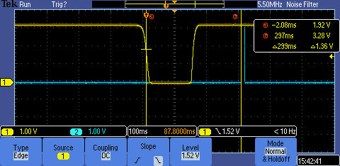
There you may notice two markers:
- Marker A is set up to the level when the button sensor line triggers a wake up interrupt (to be totally clear, an IRQ is triggered when the voltage level is below \(V_{IL} = 0.3 \cdot V_{DDIOx} \approx 1 \; V\))
- Marker B is set up the point when our application finishes its initialization (GPIO, SPI, ADC, etc.) and gets to business logic
It takes 300 ms just to get to the very beginning of the real application! That was the problem: we want to be sure that a device has been woken up by a button press. While the device was initialising itself, the button state line had reverted back and looked like there were no button press at all though. That led to the case that false positive wake ups due to noise on the button signal line were mixed with “normal” user behavior:
- an user presses the button gently
- the MCU wakes up and inits itself
- here we want to know the wake up reason: run debouncing algorithm to remove false positive wakeups
- debouncing algorithm sees that the button has been the wake up reason, but it is not pressed now — “This is due to bouncing” reports the algorithm
- the system goes to sleep
- the user is frustrated
That is not an user expects from the system ![]() .
.
Side note
That issue may be ignored and an assumption could be made that an user will just press the button harder, thus press time will be increased. But as the “tactile” piezo switch is not really tactile it is not convenient to ask a user for - you will not feel a something you would call a response from such a button, it is like you try pressing a metal part with your finger. On the oscillogram above the button pulled down the sensor line after a button touch with minimal amount of efforts - really comfortable way of pressing such buttons as we decided within the team.
So, several steps were performed to narrow and mitigate that issue.
Step 1. Find a peripheral that takes too much time to init
That step was not efficient enough:
- GPIO, ADC, SPI, I2C peripheral initialization did not require too much time to init
- ST’s USB stack initialization took ~20 ms, but optimization of that part was not a silverbullet. Getting from 300 to 280 ms wake up time still was something nice, but it was not enough
Step 2. Find a side code that influence on boot time
It was obvious, after the previous step, that long running routines should be somewhere in code that preceedes STM32L4 peripheral initialization in the very beginning of main().
That is, default CrossWorks CRT or startup code should be rather slow somewhere. After some analysis, I found the following code
in the CRT implementation of CrossWorks (should be valid for v4.4.0 and v4.5.0):
Memory copy routine
memory_copy:
    cmp r0, r1
    beq 2f
    subs r2, r2, r1
    beq 2f
1:
    ldrb r3, [r0] ;SUSPICIOUS PART
    adds r0, r0, #1
    strb r3, [r1]
    adds r1, r1, #1
    subs r2, r2, #1
    bne 1b
2:
    bx lr
Memory set routine
memory_set:
    cmp r0, r1
    beq 1f
    strb r2, [r0] ;SUSPICIOUS PART
    adds r0, r0, #1
    b memory_set
1:
    bx lr
Suspicious parts are marked and it can be seen that implemented copy and set routines make its work on per byte basis. Thus it takes 4 times greater time to copy/set memory area with the given value as STRB and STR both have a 1 cycle execution time. It is rather strange as all data should be aligned per word in memory (4 byte boundary on ARM32 platform).
If there is an assumption that CrossWorks compiler or theirs standard library may utilize unaligned data
it should be stated somewhere in the implementation of memory_copy and memory_set in my opinion.
And code above is not something you expect to get after pay some money.
Get back to our app - that CRT implementation affected us and we noticed that because of the fact we have quite large RAM memory occupation by this time - ~265 Kbyte (TCP/IP stack, TLS library, RTOS + static buffers):
-
.datasection - ~3 Kbyte -
.bsssection - ~262 Kbyte
As you know .bss section usually zeroed during CRT init routine execution and .data section, that resides in RAM,
is copied from MCU’s Flash memory.
Some calculations for STM32L4A6VG
Just to show the difference between per byte copy/set and per word copy/set implementation, I will make some calculations for CPU we used in our project - STM32L4A6VG, that operates on 4 MHz frequency after a reset event. That means: \(t_{instruction} = \frac{1}{f_{CPU}} = \frac{1}{4 \cdot 10^6} = 250 \cdot 10^{-9} \; s = 250 \; ns\)
For simplicity, let’s consider that we use only
memory_setoperation with 5 single cycle instructions within it (beq,cmp,strb,adds,b).As it sets 1 byte per an iteration and the app has to clear 265 Kbytes = 271360 bytes, it takes: \(t_{set} = C_{MEM} \cdot N = 271360 \cdot 5 = 1356800 \; cycles\)
Overall execution time:
\[T_{set} = t_{instruction} \cdot t_{set} = 250 \cdot 10^{-9} \; s \cdot 1356800 \; cycles = 0.3392 \; s \approx 0.34 \; s = 340 \; ms\]That looks quite close to the time we saw on the first oscillogram!
Expected execution time of the same routines with word wide operations: \(t_{set} = C_{MEM} \cdot N = \frac{271360}{4} \cdot 5 = 339200 \; cycles \rightarrow\)
\[\rightarrow T_{set} = t_{instruction} \cdot t_{set} = 250 \cdot 10^{-9} \; s \cdot 339200 \; cycles = 0.0848 \; s \approx 0.085 \; s = 85 \; ms\]
Applying the simple patch that should improve system’s performance:
Memory copy routine
memory_copy:
    cmp r1, r2
    itte lt
    ldrlt r3, [r0], #4
    strlt r3, [r1], #4
    bge 1f
    b memory_copy
1:
    bx lr
Memory set routine
memory_set:
    cmp r0, r1
    ite lt
    strlt r2, [r0], #4
    bge 1f
    b memory_set
1:
    bx lr
Results in the ~4 times boost of system’s wake up time:
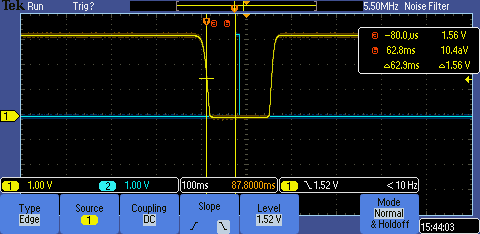
That also conform to our calculations as we reduce the number of store (STRB) operations by switching to a word basis store - store 4 bytes instead of one.
Conclusion
It is quite upsetting that non-optimal code is present in paid product like CrossWorks. Once again that issue affects all ARM Cortex-M MCUs you are working with in CrossWorks 4.4 and 4.5. Most likely users of Segger Embedded Studio are affected as well, as CrossWorks and SES shares standard library and CRT implementation.
I would like to suggest not to be afraid of digging into a vendor specific libraries if that source code available.
If you have any questions, would like me to explain something in more details or find and issue with my post, feel free to contact me via email.